T-EMSD-based p-y curve of laterally loaded piles in clay considering small-strain behavior
-
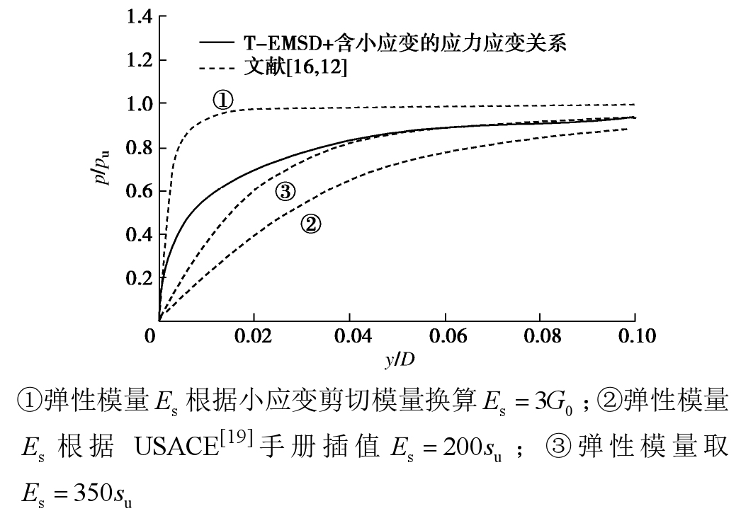
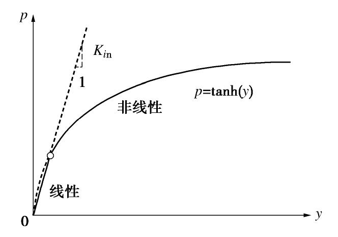
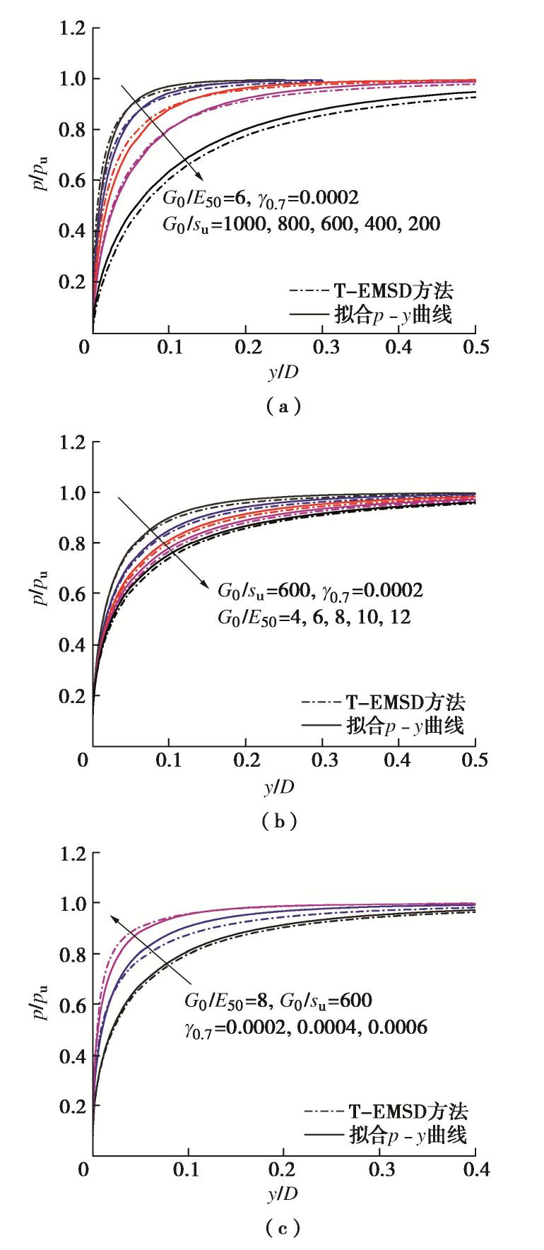
摘要: 国际主流规范API推荐p-y曲线分析海上风电钢管桩基础的水平非线性响应。该p-y曲线通过单参数刻画了土体应力应变的发展规律从而间接控制桩土非线性响应。但因过度简化,在长期使用中已暴露出低估桩侧承载力,且无法准确预测桩土初始刚度等问题。为此,首先定义了含土体小应变特性的应力应变曲线,再基于虚拟加载上限法获得考虑该土体应力应变关系的数值p-y骨干曲线。结合参数分析,拟合得到二维p-y骨干曲线表达式。进一步结合三维极限承载力系数、桩土初始刚度和剪应变系数,将p-y骨干曲线拟三维化,并分别与三维有限元和工程实例对比验证其合理性。与API规范相比,该p-y骨干曲线不但准确预测桩侧承载力,对变形控制极严的海上风电钢管桩基础而言,其更显著优点在于通过考虑土体小应变特性实现准确预测桩土初始刚度。Abstract: The international popular API code recommends the p-y curve method to analyze the nonlinear behavior of offshore wind turbine (OWT) steel pipe piles. The p-y curve controls the pile-soil nonlinear response only through one parameter regarding the development of stress-strain relation of soils. This over-simplification results in the inaccurate evaluation of the lateral initial stiffness of pile-soil and the underestimation of the bearing capacity. Therefore, the stress-strain curve with soil small-strain behavior is first introduced to achieve a numerical p-y backbone curve by using the total-displacement-loading extended mobilized strength design method (T-EMSD). The expression for the two-dimensional p-y backbone curve is then fitted from the numerical results. The three-dimensional effect of the proposed p-y curve is further considered by incorporating the three-dimensional ultimate capacity factor, the initial subgrade modulus and the compatibility factor. The rationality of the proposed p-y curve is verified against the results from the three-dimensional finite-element analysis and field tests. Compared with API code, the proposed p-y curve can provide a more reasonable prediction for both the bearing capacity and the initial stiffness of pile-soil by considering the soil small-strain behavior, which is a significant advantage for the OWT pile foundation with strict deformation control.
-
Keywords:
- laterally loaded pile /
- soft clay /
- p-y curve /
- T-EMSD method /
- small strain
-
0. 引言
西安地裂缝是20世纪50年代后期发现的,引起了人们的关注。1976年唐山地震后,西安地裂缝显著活动引起建筑物不均匀沉降而破坏。地质、工程界的研究,明确了西安地裂缝是地质构造运动而产生的认识[1-2]。20世纪80年代以来,进一步开展了西安地裂缝的原因、分布及活动规律的调查、监测研究,初步确定了其成因受南侧临潼-长安大断裂控制[2-5]。近年来,西安地裂缝活动加剧不仅受到周围地区地震作用影响,且与西安地区过量开采承压水产生相关。通过对西安地裂缝造成现有建(构)筑物破坏特征分析,地裂缝致灾机理是地裂缝上盘下沉,从而引起不均匀沉降、拉裂和错动位移,进而导致建筑物、地下洞室裂开和坍塌,路基、管道错动和断裂。同时,地表水沿地裂缝入渗和潜蚀,引起黄土湿陷不均匀沉降变形,对建(构)筑物造成二次破坏。西安地裂缝带来的危害性不仅体现在对于各类建(构)筑物生产建设的直接破坏,还会对工程场地土的性质与工程稳定性产生严重影响。从而严重地限制了建筑场地的使用,影响城市建设的合理布局[6-7, 9-10]。
对于这一特殊地质环境下的地铁隧道,特别是横穿地裂缝的隧道结构,衬砌结构沿纵向将承受比正常情况下大得多的附加应力和变形。附加作用表现为:①在地裂缝附近,上盘地层错动下沉可能脱空衬砌结构仰拱基底,或减小基底对衬砌结构的支撑作用,导致隧道衬砌发生剪切破坏;②地裂缝下盘对衬砌结构的约束作用,导致地裂缝附近衬砌结构承受拉应力;③上盘土体向下运动,引起该侧隧道结构变形,相当于弹性地基梁一端发生沉降的弯曲变形;④衬砌结构受地裂缝两侧土体的相运动,对隧道衬砌施加向下的作用力,引起隧道结构出现拉裂变形[6, 8]。地裂缝隧道设计了衬砌结构位移的预留空间[11]。由此可见,未采取措施的地裂缝隧道可能引起衬砌结构强度破坏和防水失效,不能保证正常运营。
为了揭示地裂缝隧道的力学特征和变形形态,需要分析地裂缝的产状和运动特征,以及地裂缝活动对衬砌结构的作用等。
1. 西安地裂缝分布与运动特征
西安地裂缝包括有显露地裂缝与隐伏地裂缝,是典型的黄土地区地质灾害现象。目前已发现14条地裂缝总延伸长度约103 km,分布在150 km2的黄土梁洼地貌范围内,单条地裂缝出露长度在2~12 km之间。其主要位于渭河断裂以南,临潼—长安断裂以北,向东西两侧(浐河至皂河)延伸。西安地裂缝由主裂缝、次生地裂缝和分枝地裂缝三部分组成,总体走向近似平行于临潼—长安断裂;总体倾向近似与临潼-长安断裂倾向相反,倾角约80°。西安地裂缝延伸长度可达数公里至十数公里,空间上呈不等间距平行排列,其分布范围内的地表由北向南呈逐渐升高的梁-洼地貌景观,如图1,2所示[5]。
![]() 图 2 西安地裂缝南北走向地层剖面图Figure 2. Stratigraphic profile of north-south direction of ground fissures in Xi'an
图 2 西安地裂缝南北走向地层剖面图Figure 2. Stratigraphic profile of north-south direction of ground fissures in Xi'an地裂缝大都发育在“黄土梁”地貌的南侧陡坡上这一特定地貌构造部位。其垂直位移单向累积,断距随深度的增大而增大。地裂缝发育剖面如图3所示。
2. 西安地铁隧道穿越地裂缝的设计
2.1 地裂缝最大竖向预估位移量
西安地裂缝的发展经历了从发生阶段发展至剧烈活动到成熟阶段,随后缓慢变形直至稳定这一过程。地裂缝的最大位移估算如表1所示。
表 1 西安地裂缝最大垂直预估位移量[8]Table 1. Maximum predicted vertical displacements of ground fissures(mm) 地裂缝编号 A(预估极限值) A×1.5(设计值) 地裂缝编号 A(预估极限值) A×1.5(设计值) f2 200 300 f8 100 150 f3 150 225 f10 150 225 f5 300 450 f11 300 450 f6/f6' 300(200) 450(300) f9/f9' 300(250) 450(375) f7 300 450 f12 100 150 2.2 地裂缝区间隧道结构设计
地铁隧道穿越地裂缝不可避免,应遵从以下原则:以结构措施适应变形为主前提下,在地裂缝处理段需须对结构进行分段预留必要的变形空间适应地裂缝的变形;加强断面结构抵抗变形对结构的破坏;变形缝处在结构发生变形时应当能够保持防水的效果。地裂缝活动主变形区范围根据地裂缝活动引起附近地层的活动变形范围确定为:上盘0~6 m,下盘0~4 m;微变形区上盘6~20 m,下盘4~15 m。上盘变形影响范围大于下盘。隧道衬砌结构为了适应地裂缝活动的变形应在地裂缝处应设置变形缝[6, 8]。如4, 5所示。
![]() 图 5 地裂缝隧道纵坡调整示意图Figure 5. Schematic diagram of longitudinal slope adjustment of tunnel with ground fissures
图 5 地裂缝隧道纵坡调整示意图Figure 5. Schematic diagram of longitudinal slope adjustment of tunnel with ground fissures3. 地裂缝隧道的数值分析
3.1 地裂缝隧道衬砌结构及地层条件的模型
西安地铁二号线地裂缝区段隧道一般采用马蹄形隧道断面,以正交穿越地裂缝的地铁2号线为分析对象,地裂缝区间隧道采用CRD开挖方法,最大断面净空宽为8.3 m,高为8.45 m;初衬为C25喷射混凝土,厚30 cm;二衬为C30模注钢筋混凝土,厚50 cm。衬砌结构沿纵向每10 m或15 m预设10 cm宽的变形缝,充填密封防渗材料封闭变形缝。以便衬砌结构适应地裂缝上下盘土体相对运动,避免衬砌结构附加拉应力,防止基底出现脱空现象。并且在衬砌结构端部局部加厚以便适应可能出现的应力集中现象。
西安地铁地裂缝隧道通过FLAC-3D有限差分软件建立了计算模型。计算模型隧道埋深为10 m,横断面内水平向宽度为80 m,竖向高度为60 m,轴向长度为200 m。模拟地层埋深0~7.5 m为晚更新世风积黄土,埋深7.5~25.5 m为晚更新世粉质黏土及古土壤层,埋深25.5~30.5 m为中更新世黄土及古土壤层,以及埋深30.5 m以下为中更新世粉质黏土。地裂缝采用库仑摩擦接触面模拟;应力应变关系采用莫尔-库仑屈服条件的弹塑性模型描述;地层及二次衬砌结构采用实体单元模拟;初期衬砌结构采用壳单元模拟。
在地裂缝活动导致自由场地地面不均匀沉降如图6所示条件下,衬砌结构错动位移如图7,8和图9所示。衬砌结构变形缝最大挤压变形为3.6 cm,位于地裂缝处变形缝两侧衬砌拱底;最大张拉变形为5.7 cm,位于上盘内邻近地裂缝衬砌结构变形缝的拱底处。衬砌结构变形缝预留10 cm,满足最大挤压变形的要求。衬砌结构大、小主应力如图10,11所示。大主应力受拉的集中区域主要分布在衬砌结构内侧腰部,最大值为2.02 MPa;小主应力受拉的区域也分布于此。地裂缝两侧衬砌结构内侧腰部受拉,应进行加强处理。隧道衬砌结构采用C30混凝土,其抗压强度为30 MPa,抗拉强度为2.01 MPa,添加钢纤维可满足受拉的强度要求。
![]() 图 6 地裂缝自由场地地表沉降Figure 6. Surface settlements of free site under acting ground fissures
图 6 地裂缝自由场地地表沉降Figure 6. Surface settlements of free site under acting ground fissures![]() 图 7 隧道衬砌拱顶纵轴线沉降分布曲线Figure 7. Distribution of settlement at arch of lining structure and on surface
图 7 隧道衬砌拱顶纵轴线沉降分布曲线Figure 7. Distribution of settlement at arch of lining structure and on surface![]() 图 8 隧道衬砌结构顶、底水平位移分布曲线Figure 8. Distribution of horizontal displacement at vault and arch bottom of lining structure along axial direction of tunnel
图 8 隧道衬砌结构顶、底水平位移分布曲线Figure 8. Distribution of horizontal displacement at vault and arch bottom of lining structure along axial direction of tunnel![]() 图 9 地裂缝附近隧道衬砌结构变位示意图Figure 9. Differential settlements of segmented lining near ground fissures
图 9 地裂缝附近隧道衬砌结构变位示意图Figure 9. Differential settlements of segmented lining near ground fissures4. 地裂缝隧道结构与轨道工程措施
在地裂缝区间段隧道运行100 a后,地裂缝会导致隧道下沉500 mm。为保证隧道具有列车运行的空间,在隧道截面扩构段,二衬结构加大截面厚度及增加配筋,提高纵向分布筋直径及间距的方法抵抗扭转、剪切对结构的影响。地裂缝隧道段的初期支护和内衬之间增设沥青混凝土复合衬砌,在初期支护和二次衬砌之间形成夹层,利用沥青混凝土特有的延展性、流变性,密封衬砌结构变形缝。随着地裂缝活动,沥青混凝土在围岩压力作用下沿侧向产生挤出变形,从围岩压力大的部位向围岩压力小的部位流动,使得围岩压力趋于均匀化。当地裂缝活动导致衬砌结构错动变形时,沥青混凝土易产生流变剪切变形,适应衬砌结构变形缝的变化,可发挥其防渗能力。沥青混凝土变形缝构造与变形模型试验结果如图12,13所示。
![]() 图 12 加筋沥青混凝土防渗变形缝结构Figure 12. Scheme of reinforced asphalt concrete and anti-seepage deformation joint structure
图 12 加筋沥青混凝土防渗变形缝结构Figure 12. Scheme of reinforced asphalt concrete and anti-seepage deformation joint structure5. 结论
(1)西安临潼—长安断裂带是地裂缝产生的构造活动,过量开采承压水产生不均匀沉降是地裂缝发展的附加作用。准确预测地裂缝的位移量,是地裂缝隧道结构设计的重要依据。
(2)西安地铁二号线地裂缝影响段65 m设变形缝,在地裂缝影响范围内,主变形段通常占地裂缝80%~90%的总垂直位移量,是主要的设防区,按10 m进行隧道分段。微变形段垂直位移量仅占10%~20%的总位移量,按10~15 m进行隧道分段。
(3)地裂缝隧道结构应采取衬砌结构适应地裂缝变形的原则。在地裂缝处理段需对结构进行分段,预留必要的变形空间作为变形缝以适应地裂缝的变形。加强变形缝断面的结构,以便满足抵抗变形对结构破坏的要求。
(4)衬砌结构内侧拱腰分布拉应力集中区,需提高衬砌结构混凝土的抗拉强度。采取加筋沥青混凝土复合衬砌及沥青玛蹄脂填充变形缝处理,可改善衬砌结构受力条件,密封衬砌结构变形缝,保持防水的效果。
-
![]()
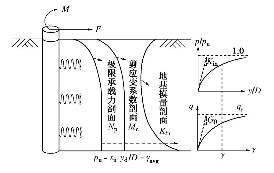
图 5 水平受荷桩拟三维分析
Figure 5. Construction of p-y curve considering three-dimensional effects
表 1 剪应变系数
Table 1 Values of compatibility factor
 下载: 导出CSV
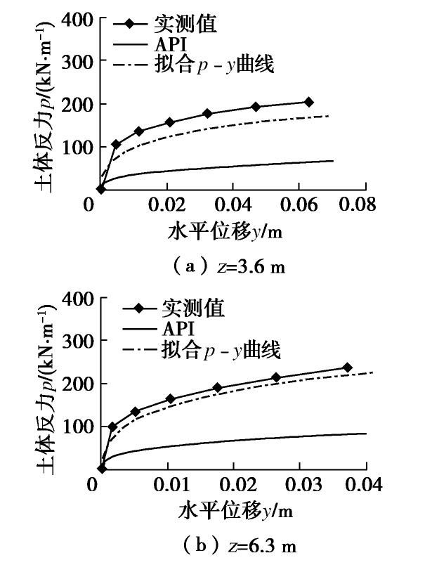
表 2 现场试验1土体参数
Table 2 Soil parameters of field test Case 1
深度z/D /kPa /MPa /(10-4) /MPa 2 18 10 1 1.8 4 20 14 1 2
下载: 导出CSV
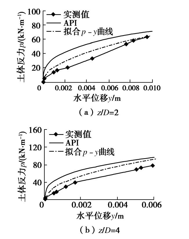
表 3 现场试验2土体参数
Table 3 Soil parameters of field test Case 2
深度z/m /kPa /MPa /(10-4) /MPa 3.6 13 12 4 0.87 6.3 15 15 4 1.0
下载: 导出CSV
-
[1] DNV. Design of Offshore Wind Turbine Structures: DNV—OS—J101[S]. 2014.
[2] American Petroleum Institute (API). Recommended practice for planning, designing and constructing fixed offshore platforms—working stress design[C]//API 2A-WSD, twenty-second ed. Washington, D.C, 2014.
[3] MATLOCK H S. Correlation for design of laterally loaded piles in soft clay[C]//Proceedings Second Annual Offshore Technology Conference. Houston, 1970: 1204.
[4] 朱斌, 熊根, 刘晋超, 等. 砂土中大直径单桩水平受荷离心模型试验[J]. 岩土工程学报, 2013, 35(10): 1807-1815. https://www.cnki.com.cn/Article/CJFDTOTAL-YTGC201310007.htm ZHU Bin, XIONG Gen, LIU Jin-chao, et al. Centrifuge modelling of a large-diameter single pile under lateral loads in sand[J]. Chinese Journal of Geotechnical Engineering, 2013, 35(10): 1807-1815. (in Chinese) https://www.cnki.com.cn/Article/CJFDTOTAL-YTGC201310007.htm
[5] 王卫, 闫俊义, 刘建平. 基于海上风电试桩数据的大直径桩p-y模型研究[J]. 岩土工程学报, 2021, 43(6): 1131-1138. https://www.cnki.com.cn/Article/CJFDTOTAL-YTGC202106023.htm WANG Wei, YANG Jun-yi, LIU Jian-ping. Study on p-y models of large-diameter pile foundation based on in-situ tests of offshore wind power[J]. Chinese Journal of Geotechnical Engineering, 2021, 43(6): 1131-1138. (in Chinese) https://www.cnki.com.cn/Article/CJFDTOTAL-YTGC202106023.htm
[6] 黄茂松, 俞剑, 张陈蓉. 基于应变路径法的黏土中水平受荷桩p-y曲线[J]. 岩土工程学报, 2015, 37(3): 400-409. https://www.cnki.com.cn/Article/CJFDTOTAL-YTGC201503003.htm HUANG Mao-song, YU Jian, ZHANG Chen-rong. p-y curves of laterally loaded piles in clay based on strain path approach[J]. Chinese Journal of Geotechnical Engineering, 2015, 37(3): 400-409. (in Chinese) https://www.cnki.com.cn/Article/CJFDTOTAL-YTGC201503003.htm
[7] ASHOUR M, NORRIS G. Modeling lateral soil-pile response based on soil-pile interaction[J]. Journal of Geotechnical and Geoenvironmental Engineering, 2000, 126(5): 420-428. doi: 10.1061/(ASCE)1090-0241(2000)126:5(420)
[8] OSMAN A S, BOLTON M D. Simple plasticity-based prediction of the undrained settlement of shallow circular foundations on clay[J]. Géotechnique, 2005, 55(6): 435-447. doi: 10.1680/geot.2005.55.6.435
[9] YU J, HUANG M S, LI S, et al. Load-displacement and upper-bound solutions of a loaded laterally pile in clay based on a total-displacement-loading EMSD method[J]. Computers and Geotechnics, 2017, 83: 64-76. doi: 10.1016/j.compgeo.2016.10.025
[10] YU J, ZHU J L, SHEN K M, et al. Bounding-surface-based p-y model for laterally loaded piles in undrained clay[J]. Ocean Engineering, 2020, 216: 107997. doi: 10.1016/j.oceaneng.2020.107997
[11] BENZ T, VERMEER P A, SCHWAB R. A small-strain overlay model[J]. International Journal for Numerical and Analytical Methods in Geomechanics, 2009, 33(1): 25-44. doi: 10.1002/nag.701
[12] KLAR A, OSMAN A S. Load-displacement solutions for piles and shallow foundations based on deformation fields and energy conservation[J]. Géotechnique, 2008, 58(7): 581-589. doi: 10.1680/geot.2008.58.7.581
[13] 黄茂松, 李森, 俞剑. 水平受荷桩的弹性有限元虚拟加载上限分析[J]. 岩土力学, 2016, 37(8): 2399-2403, 2410. https://www.cnki.com.cn/Article/CJFDTOTAL-YTLX201608036.htm HUANG Mao-song, LI Sen, YU Jian. Analysis of laterally loaded pile by elastic finite element based EMSD method[J]. Rock and Soil Mechanics, 2016, 37(8): 2399-2403, 2410. (in Chinese) https://www.cnki.com.cn/Article/CJFDTOTAL-YTLX201608036.htm
[14] LI S, YU J, HUANG M S, et al. Application of T-EMSD based p-y curves in the three-dimensional analysis of laterally loaded pile in undrained clay[J]. Ocean Engineering, 2020, 206: 107256. doi: 10.1016/j.oceaneng.2020.107256
[15] LI S, HUANG M S, YU J. Continuous field based upper-bound analysis for the undrained bearing capacity of strip footings resting near clay slopes with linearly increased strength[J]. Computers and Geotechnics, 2019, 105: 168-182. doi: 10.1016/j.compgeo.2018.10.002
[16] LI S, YU J, HUANG M S, et al. Upper bound analysis of rectangular surface footings on clay with linearly increasing strength[J]. Computers and Geotechnics, 2021, 129: 103896. doi: 10.1016/j.compgeo.2020.103896
[17] HUANG M S, LI S, YU J, et al. Continuous field based upper bound analysis for three-dimensional tunnel face stability in undrained clay[J]. Computers and Geotechnics, 2018, 94: 207-213. doi: 10.1016/j.compgeo.2017.09.014
[18] KLAR A. Upper bound for cylinder movement using “elastic” fields and its possible application to pile deformation analysis[J]. International Journal of Geomechanics, 2008, 8(2): 162-167. doi: 10.1061/(ASCE)1532-3641(2008)8:2(162)
[19] USACE. Settlement analysis, Engineer Manual EM 1110-1-1904. U.S. Army Corps of Engineers: Washington, D.C. 1990.
[20] GEORGIADIS M, ANAGNOSTOPOULOS C, SAFLEKOU S. Cyclic lateral loading of piles in soft clay[J]. Geotechnical Engineering, 1992, 23(1): 47-60.
[21] JEANJEAN P. Re-assessment of p-y curves for soft clays from centrifuge testing and finite element modeling[C]//Offshore Technology Conference. Houston, 2009.
[22] DUNNAVANT T W, O'NEILL M W. Experimental p-y model for submerged, stiff clay[J]. Journal of Geotechnical Engineering, 1989, 115(1): 95-114. doi: 10.1061/(ASCE)0733-9410(1989)115:1(95)
[23] BYRNE B W, HOULSBY G T, BURD H J, et al. PISA design model for monopiles for offshore wind turbines: application to a stiff glacial clay till[J]. Géotechnique, 2020, 70(11): 1030-1047. doi: 10.1680/jgeot.18.P.255
[24] ZHANG C R, YU J, HUANG M S. Winkler load-transfer analysis for laterally loaded piles[J]. Canadian Geotechnical Journal, 2016, 53(7): 1110-1124. doi: 10.1139/cgj-2015-0394
[25] YU J, HUANG M S, ZHANG C R. Three-dimensional upper-bound analysis for ultimate bearing capacity of laterally loaded rigid pile in undrained clay[J]. Canadian Geotechnical Journal, 2015, 52(11): 1775-1790. doi: 10.1139/cgj-2014-0390
[26] ZHANG Y H, ANDERSEN K H, TEDESCO G. Ultimate bearing capacity of laterally loaded piles in clay-Some practical considerations[J]. Marine Structures, 2016, 50: 260-275. doi: 10.1016/j.marstruc.2016.09.002
[27] FAN C C, LONG J H. Assessment of existing methods for predicting soil response of laterally loaded piles in sand[J]. Computers and Geotechnics, 2005, 32(4): 274-289. doi: 10.1016/j.compgeo.2005.02.004
[28] KIM Y, JEONG S, LEE S. Wedge failure analysis of soil resistance on laterally loaded piles in clay[J]. Journal of Geotechnical and Geoenvironmental Engineering, 2011, 137(7): 678-694. doi: 10.1061/(ASCE)GT.1943-5606.0000481
[29] SUN C G, CHO C S, SON M, et al. Correlations between shear wave velocity and in-situ penetration test results for Korean soil deposits[J]. Pure and Applied Geophysics, 2013, 170(3): 271-281. doi: 10.1007/s00024-012-0516-2
-
期刊类型引用(4)
1. 史治文. 西安地铁八号线地裂缝隧道暗挖施工技术与沉降控制措施研究. 结构工程师. 2024(05): 137-142 .  百度学术
百度学术
2. 秦璐. 考虑地裂缝影响的盾构隧道变形破坏机制试验研究. 九江学院学报(自然科学版). 2023(03): 47-51 . 百度学术
3. 苗晨阳,黄强兵,苟玉轩,滕宏泉,贾少春. 地裂缝场地盾构隧道下穿施工对既有管廊的影响研究. 现代隧道技术. 2022(03): 155-165+171 . 百度学术
4. 赵阳川. 某铁路隧道衬砌裂缝对结构安全的影响分析. 工程建设与设计. 2022(17): 97-101 . 百度学术
其他类型引用(2)


计量
- 文章访问数: 327
- HTML全文浏览量: 52
- PDF下载量: 225
- 被引次数: 6